TL;DR: AgentPad13 is an open-source take on the $230 Codex Micro and a test of whether an autonomous scientist can teach itself PCB routing. We wanted a more wallet-friendly, open-source Codex Micro, so we asked Marvin to take a crack at it. Within 48 hours, it had researched PCB routing, learned from why existing tools failed, and completed and simulated the board. Check out the configurator and build your own here!
Why we built AgentPad13
The Codex Micro is a pretty sweet gadget: a programmable macropad that gives coding agents a physical presence through dedicated keys and status lights. We wanted one but not only was it priced at a hefty $230, it sold out pretty much immediately.1
So we decided to build an open version that would retain the general feature set and elegant design language, could work with different coding agents, uses standard switches and firmware, and cost as little as possible for a complete device. The problem? We had no idea what the hell we were doing. PCB was completely new territory for us and our relevant experience could be charitably summed up as building simple circuits, basic (and very ugly) soldering, and whatever we still retained from high-school physics (right hand rule?).
That said, the project also gave us an excuse to test something more interesting. Marvin is designed to be an autonomous scientist: it reviews literature, synthesizes prior work, generates hypotheses, runs experiments, and carries what it learns into the next iteration. We wanted to know whether that process would still work on a problem outside Marvin’s usual applications and frankly, well outside the scope of what we originally built Marvin to do.
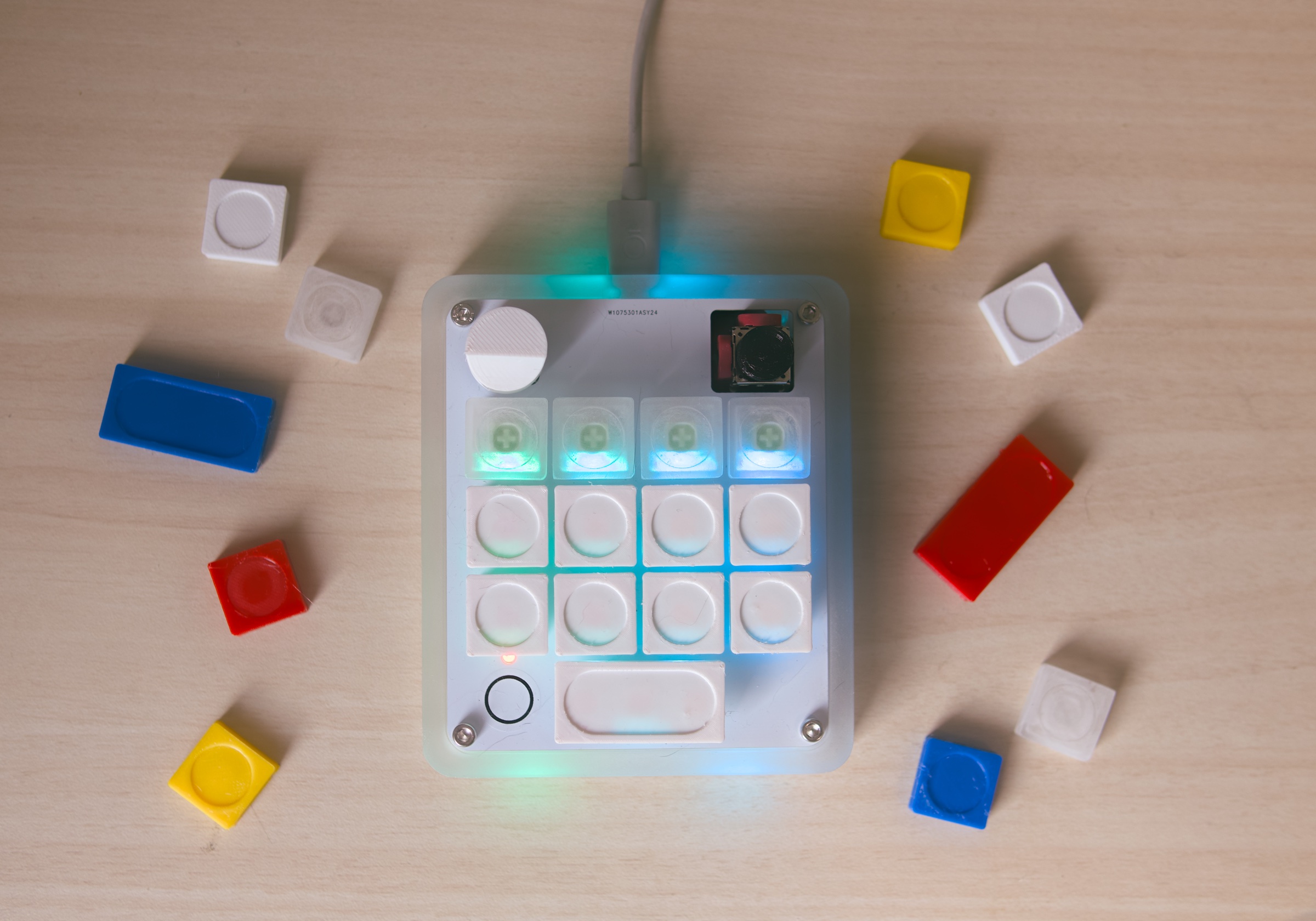
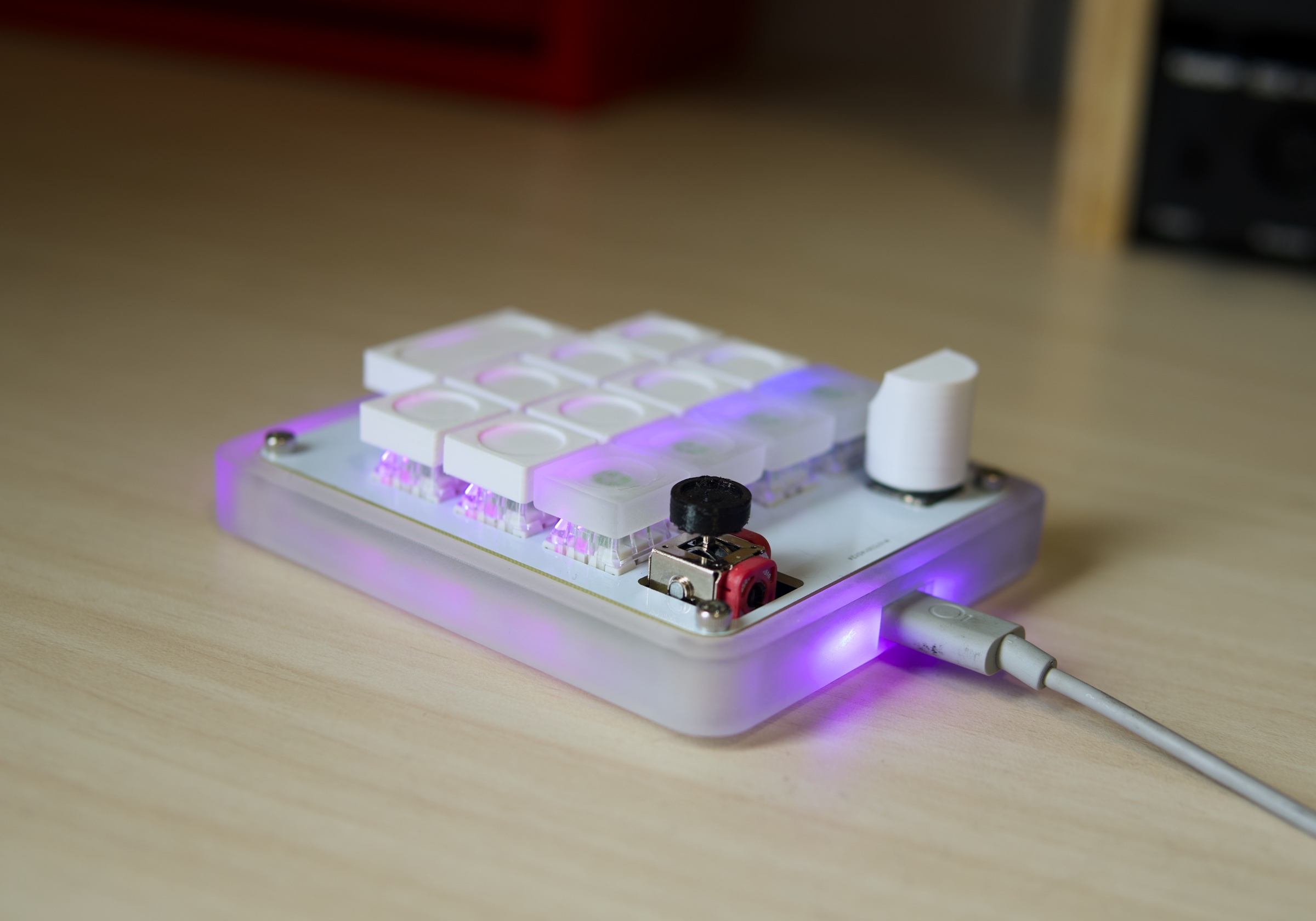
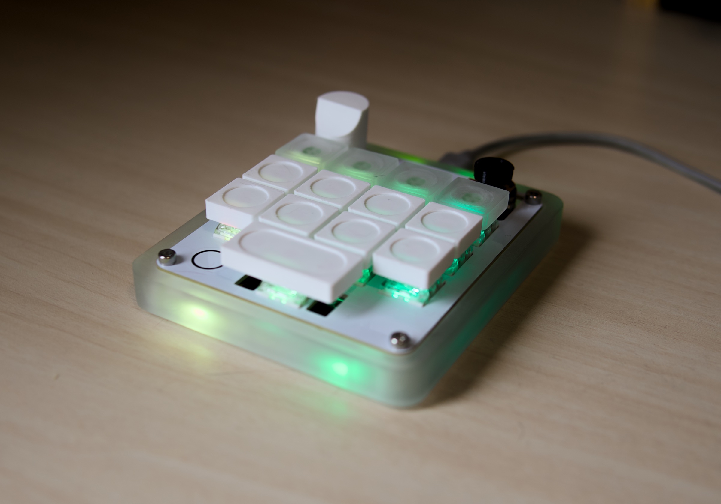
The result is AgentPad13, with 13 hot-swappable keys, a rotary encoder, an analog joystick, capacitive touch, per-key RGB, edge lighting, QMK/Vial firmware, and an open agent-status protocol.
Where the existing routers fell short
For the overall circuit itself, we found both Fable 5 and GPT-5.6 Sol were more than up to the tasks of scoping out and planning out the wiring and BOM. But what makes electrical engineering as much art as science is the tactful interplay of placing components on a constrained plane and routing said wiring between them.
We started with the usual suspects, using KiCad and FreeRouting through a highly regarded open-source skill called KiCadRouter. These tools were useful for constructing the board, enforcing design rules, and routing most of the connections, but every attempt eventually plateaued. We turned next to Quilter, a commercial AI PCB-design service, and got much the same result. Its best attempt left 19 of 353 connections unfinished, while our best FreeRouting run reached 18. Both were close to 95% complete.
Quilter’s result also depended on compromises we could not accept. It routed the 5V supply at roughly 0.153 mm instead of the required 0.5 mm, placed copper too close to mounting holes, and returned a USB pair that was no longer meaningfully paired. The board looked closer to completion, but only because it had stopped solving the same manufacturing problem.
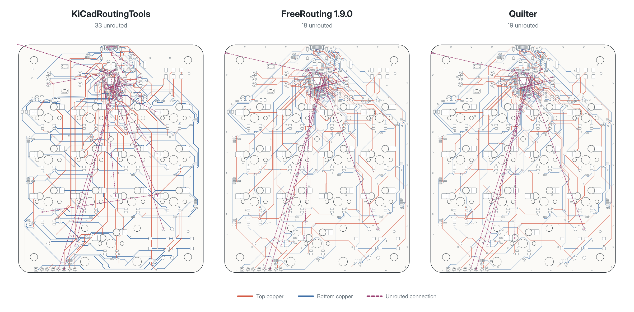
Unfortunately, PCB routing gets harder as it approaches completion. It’s easy to route traces when you’re dealing with wide open real estate, but each remaining trace has to fit around everything already routed, so the last few connections are usually the ones with the fewest viable paths. In our case, they were concentrated around the RP2040 and the long routes crossing the switch field, where every new connection competed with dense component placement and hundreds of existing traces.
There was a quick shortcut that would’ve gotten us there much more easily and likely would’ve worked fine with the aforementioned tools. PCB boards can be made with different numbers of layers, each of which allows for traces to “criss cross” each other, like overpasses on interstate. More layers stacked up, more criss crossing allowed and easier routing. However, since cost effectiveness was an explicit goal for this project, we insisted on our design being a 2-layer PCB instead of 4-layer, which would’ve raised the price by roughly 50%. That’s also why we capped the max dimension of our board at 100mm as fabs often charge more past that threshold.
Turning routing into a research problem
At this point, we asked Marvin to stop treating the router as an oracle and approach the problem as research instead. Marvin reviewed the existing open-source tools, academic placement and routing work, KiCad documentation, manufacturer rules, component datasheets, community PCB guides, and the layouts of working open-source keyboards. Like synthesizing a vast corpus of peer-reviewed literature, Marvin put together this research into a runbook and also surfaced a number of “routing 101” conventions that existing tools had missed. The purpose, as Marvin put it, was to avoid “re-inventing decades of human experience, best practices, and institutional knowledge.”
It then turned that research into experiments on our board. Each attempt tested a specific strategy, recorded what improved, identified any new regressions, and carried the result into the next iteration. Progress was measured against the complete design rather than the number of remaining connections: a run did not count as better if it reduced the unrouted total while breaking USB, narrowing a power trace, moving a frozen component, or introducing a manufacturing violation. That distinction mattered because the previous tools had already shown that a better-looking unrouted traces number could ultimately describe a worse board.
Crucially, Marvin’s experimental approach mapped perfectly to our scientific infrastructure for long-running project tracking and logic trails. Marvin traced the hierarchy of experimental placements like a decision tree, and was able to backtrack successfully when a hypothesis plateaued and combine learnings from different attempts together.
What Marvin learned
Routing order made a substantial difference. Power needed to be routed early and kept wide so ordinary signals could not consume the space it required. Critical connections such as USB and the flash bus also needed reserved corridors rather than being left for a general-purpose router to recover later.
Marvin initially hypothesized that power should run around the board’s perimeter, preserving the center for difficult signals. It then measured the layouts of shipped open-source keyboards and found that they generally used wide, direct power routes through the center. The perimeter rule was discarded, while the broader lesson, route power early and protect scarce corridors, survived.
Placement turned out to be equally important. Our original MCU cluster was much denser than comparable working RP2040 boards, leaving too little room for traces to escape the chip. Marvin spread the supporting components, moved related endpoints closer together, reserved a direct corridor for the flash bus, and treated interchangeable GPIO assignments as variables rather than permanent decisions. When moving a signal to a neighboring pin simplified the copper, the firmware map followed the finished board.
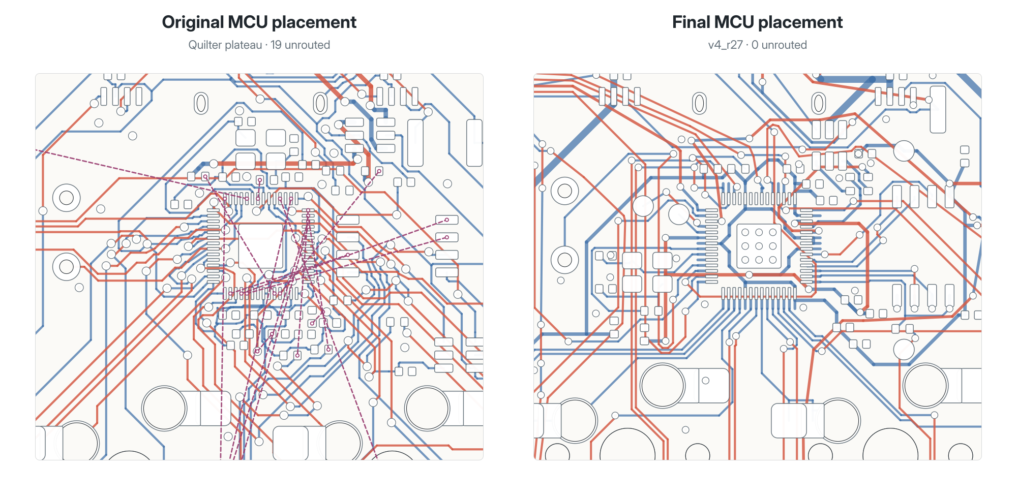
Marvin also stopped asking one router to solve everything simultaneously. The board was divided into stages for critical signals, power, flash, remaining signals, and finally ground. Successful copper was locked before the next stage, while failed routes named the specific placement, pin assignment, or neighboring trace that needed to change. This preserved working regions and turned each failure into a smaller, better-defined experiment.
A completed board and a reusable workflow
At last, our board reached zero unrouted connections and zero design-rule violations under the actual manufacturing constraints. The final result also passed the checks for power width, USB connectivity, component placement, board geometry, and capacitive-touch area. Marvin also applied the electrical and manufacturing practices it found during that research, including proper USB-C configuration and protection, voltage shifting for the LEDs, ground planes, fabrication clearances, component-to-footprint checks, and verified assembly packages. It built the firmware and simulated the compiled UF2 against the switches, encoder, joystick, touch input, and all 24 LEDs before the hardware arrived.
For the creation of AgentPad13, the best agentic routing workflow we could find ended up being the one Marvin developed for itself. That’s not to say this is the end-all-be-all for agentic PCB routing. There are surely many, many applications where engineering challenges and requirements where this workflow will also fall short. But it’s still a remarkable result in and of itself. What it demonstrates is that an agentic scientist like Marvin can enter an unfamiliar domain, learn from the available knowledge, improve through experiments and controlled regression tracking, and leave behind a method that can be reused and extended.2
The bubble-wrapped moment of truth arrives
The boards have now been fabricated and assembled, and drumroll… they actually work! And in our humble opinion, the keyboards look fantastic in all of their RGB glory.
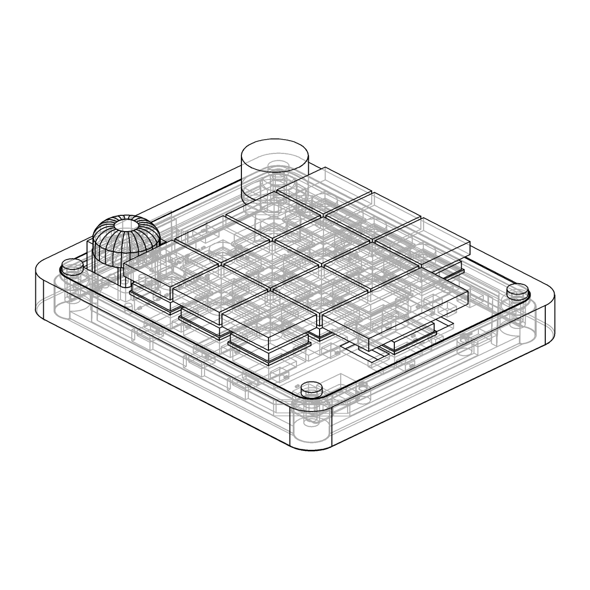
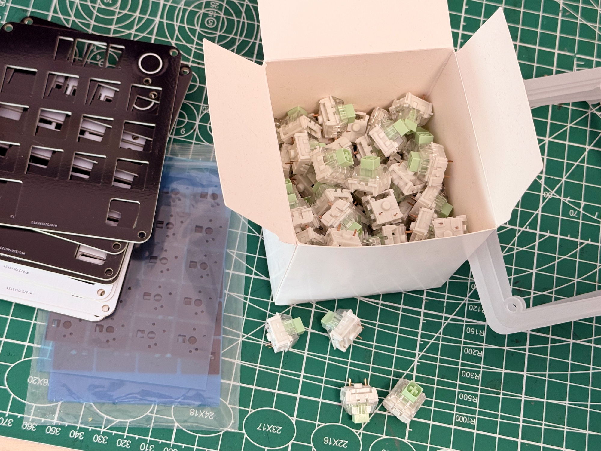
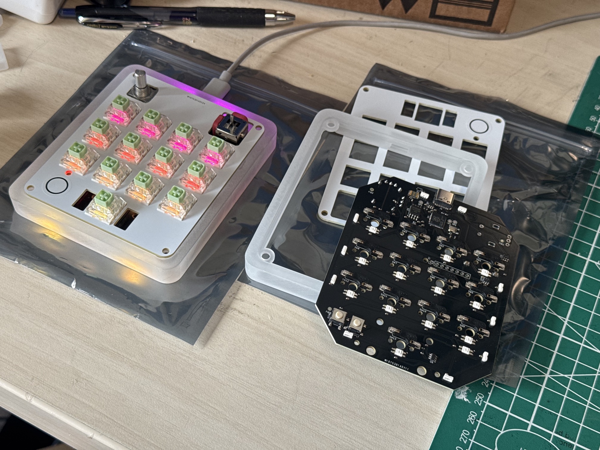
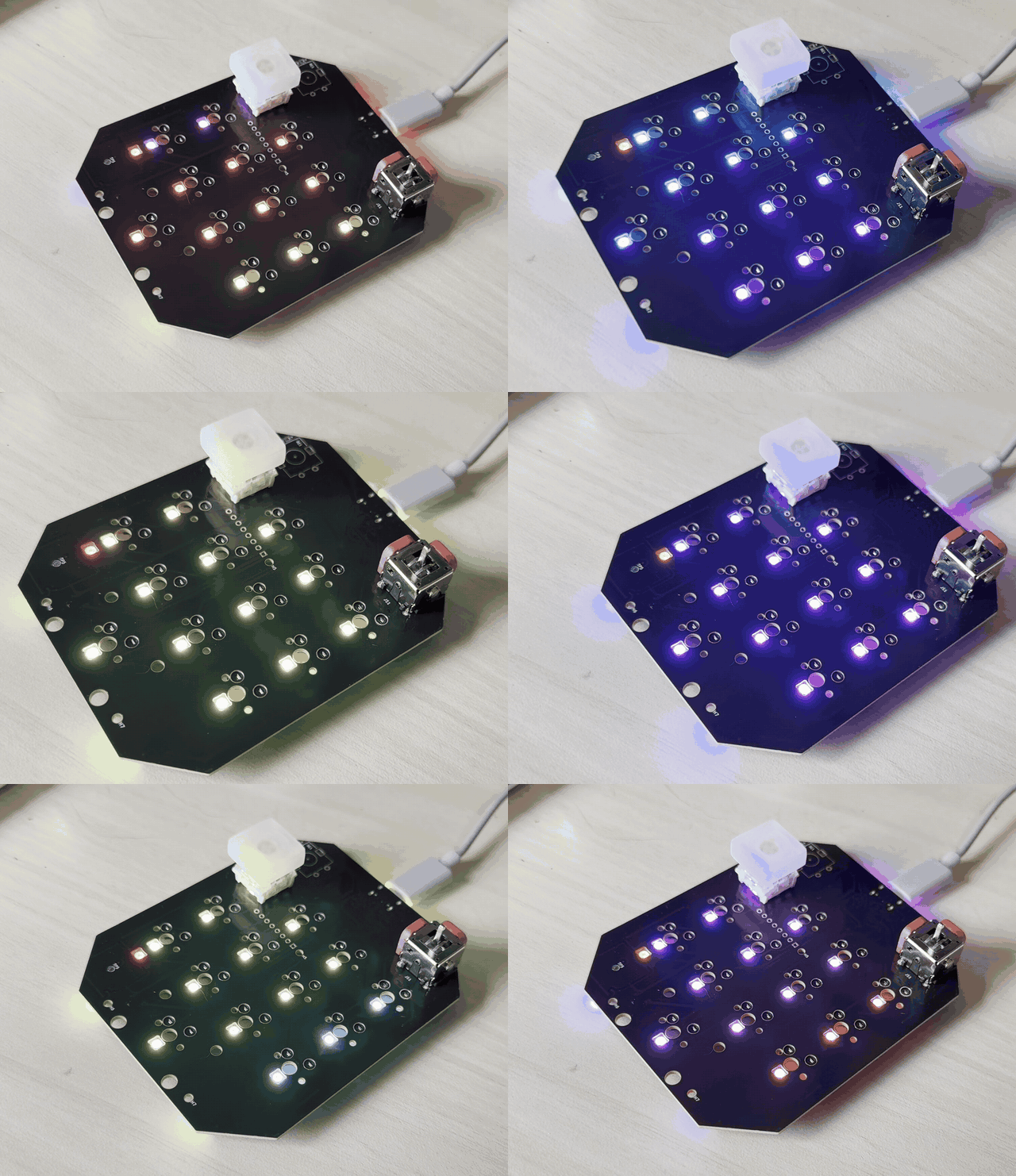
Marvin did make one visible hardware mistake: the two lower underglow LEDs point away from the board instead of inward. They still illuminate, but mostly in the wrong direction. This was a footprint-orientation error rather than a routing problem, and it has been corrected in the next revision. The case CAD also revealed some mirroring problems that we have since fixed and added checks to prevent.
As for the final cost, the assembled electronics actually came in under estimates at around $35 per fully populated board. We sprang for some snazzy frosted resin cases and key caps and FR4 top plates, but even with those parts, total cost was around $65 per unit. A complete build will vary depending on your configuration in terms of switches, keycaps, lighting, and how much you can 3D print at home.
Build your own
AgentPad13 is free and open source. The PCB, case, firmware, manufacturing files, and build instructions are available on GitHub, along with a configurator so you can customize your color scheme and grab the appropriate files and parts list for each build.
We’re already seeing some community contributions3 and hope people will continue to build on this project. Some potential next steps include a lightweight app to connect to multiple coding agents, an optional OLED screen, and a base that can double as bluetooth and battery for wireless functionality.
So if you have an interesting problem that existing tools can almost, but not quite, solve, try Marvin and let us know what cool problems you’re tackling with it!
-
OpenAI lists the Codex Micro at $230 and currently marks it as out of stock. ↩
-
Speaking of which, we plan to release this routing skill as an open-source package. ↩
-
Shout out to @lop1381997 for Direct OAI firmware, a variant that enables native Codex compatibility. ↩